RiverDave
In it to win it
- Joined
- Sep 13, 2007
- Messages
- 126,718
- Reaction score
- 166,339
Still waiting for Dave to send some shirts my way [emoji12]
did your order them? I am pretty sure we have caught up with all orders now?


Still waiting for Dave to send some shirts my way [emoji12]
did your order them? I am pretty sure we have caught up with all orders now?


.jpg")
Roughly marked out the dash.
View attachment 529821
Was going to cut it out but missing a 82mm holesaw for the tacho.
By the time u put in a steering wheel and navigator seat there's not much room on the dash to put much.
I thought of maybe getting some of them Can Mount gauges but I thought it would look wanky.
View attachment 529822
So I'm running a
Tacho
Coolant temp
Oil pressure
Volts
Hrs
And for switches
Fuel pump on/off
Coolant Temp pos1/pos2 (switching between cylinder heads)
Bilge Pump on/off
Bilge Blower on/off
Wet Exhaust on/off/auto (auto will come on at ~2000rpm of the engine)
I'll sneak the ignition between the steering wheel n tacho and put a cigarette lighter in somewhere where it fits.
Stereo can go in the side wall between the navi and back seat. Wouldn't mind a GPS in there somewhere but that's years off.
There's a spot up the nose of the boat where I'm thinking of putting the fuses I can put it.If it helps, no need for the hour meter on the dash, mine and most I've seen are mounted back by the engine.


.jpg")

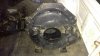
There is a mercuiser plate that'll pack it out but I ain't pulling the flywheel off to put it on, stuff that.That's good enough on the alignment, rubber couplers are always off a little due to the nature of the beast. I'd have an aluminum shim of the needed thickness made to fit between the bellhousing and the block somewhere along the line.
Yeah I've had a few comments about that HEI distributor. Same with that intake manifold, I'll look at getting rid of them once it's all going.I'm sure I have enough thunderbolt v stuff to fix you up. It'll treat you a lot better than the auto HEI. I'll be sending a couple powerheads back under I can throw it in the shipping mix.


.jpg")


Now for the money shots.
View attachment 531077 View attachment 531078 View attachment 531079 View attachment 531080
The drives getting a new skeg put on it this weekend.Come on man! Stuff that drive in it and get yo azz to the lake! !!!
Lookin good jimmy!
When I first looked at your post with the pictures, I was concentrating on the boat. After taking another look, the countryside is absolutely gorgeous man. Wow!
")
Said no one everVictoria is not bad BUT NSW is much better.
It's dry as a chip at the moment. Stew has a good view hey! That's the side of town I wanted to build but it was going to cost too much for a first house.When I first looked at your post with the pictures, I was concentrating on the boat. After taking another look, the countryside is absolutely gorgeous man. Wow!
Yeah I rang my local marine guy the other day and he said the same thing.If that is a 400 run a 160 t stat and I'd set the light to come on at 185. 15 psi for the oil light.


That was my first thought. I rang a few guys and they said it shouldn't matter as long as its still level and it's got bowls/floats on both ends.you can just rotate the carb 180*
Just move the pivot ball to the top of the linkage.


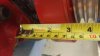
That's a lot of numbers on that measuring stick
.jpg")


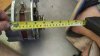
I got a mechanical engineer mate, I might get him to come check it out, get a professional opinion.Somewhere down there there has to be a set of 'Cruiser engine mounts. Those don't make me feel all warm and fuzzy.
http://www.ebay.com.au/itm/Mercruis...562402?hash=item25cd43cc22:g:-Z8AAOSw5cNYeaFe
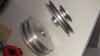
This was my thought as well. However, if you dont have a lathe, and if you could find a grade 8 half inch bolt long enough, you might be able to use one inch .250 wall aluminum tubing in between to strengthen it.That does look at little scary. If you got a piece of solid bar stock 1.250 or 1.5 in put it in a lathe and drill a hole in the center sink on both ends for the nuts slide it over the all thread put the rubber isolator between the sleeve and motor plate that would be a lot stronger.
That does look at little scary. If you got a piece of solid bar stock 1.250 or 1.5 in put it in a lathe and drill a hole in the center sink on both ends for the nuts slide it over the all thread put the rubber isolator between the sleeve and motor plate that would be a lot stronger.
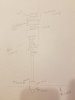
What I'd do is measure as it sits now bottom of the foot to the bottom of the rubber.This was my thought as well. However, if you dont have a lathe, and if you could find a grade 8 half inch bolt long enough, you might be able to use one inch .250 wall aluminum tubing in between to strengthen it.


I can't see the attachment, but I can see your drawing, and I like this design much better. Make sure you use grade 8 washers between the castle nuts and the aluminum mounts. Keeping that assembly tight will be key, so I wouldn't be afraid to use a second Jam nut if I were you. Probably Overkill, but might be worth it.What I'd do is measure as it sits now bottom of the foot to the bottom of the rubber.
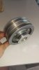
Undo the pre-load off the rubber bush.
Measure from the top of the rubber to the bottom of the foot and that will be my sleeve length.
Do away with the 2 nuts put the sleeve in and pre-load the the rubber back to first measurement.
View attachment 532524
Yeah I've left a heap of thread underneath, so I can sneak another nyloc nut on top and bottom.I can't see the attachment, but I can see your drawing, and I like this design much better. Make sure you use grade 8 washers between the castle nuts and the aluminum mounts. Keeping that assembly tight will be key, so I wouldn't be afraid to use a second Jam nut if I were you. Probably Overkill, but might be worth it.