obnoxious001
Engine building character
- Joined
- Dec 28, 2007
- Messages
- 6,599
- Reaction score
- 4,083
I recently built a matched pair of 489 cubic inch engines for an RDP member. I will leave it to him to identify himself if he sees fit. With some minor variations, these build instructions could apply to most marine performance engine builds. They left here as long blocks, but were destined to get Pro Chargers installed on them before they went into the boat. Here’s the story of how they got built.
First, a bit of background on myself for those who are new or don’t have a clue who I am. I grew up around boats and boat racing, although my family never owned a boat. We got involved with the Pasadena Boat and Ski Club and went to various water ski and other boat racing events. Back then, one boat would serve as family boat, ski race boat, drag race boat and also run endurance races like the Parker 9 Hour. Through mutual friends, my dad met Lou Brummett who was building and racing the Mandella boats. The shop was close to our home so we spent quite a bit of time there, where I met Louis Unser, who was building Lou’s Ford race engines. Between those times and the shop and various water ski outings, my direction for the future was set. I would eventually get into water ski racing and engine building.
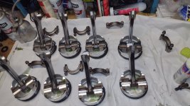
Before I start with all the details, a couple of quick notes about “Balance and Blueprint” To properly balance a rotating assembly for an engine, each combination of a piston, wrist pin, pin locks, connecting rod, connecting rod bearings and piston rings should weigh the same amount. Each of the 8 pistons for our V8 engine gets weighed and lighten to match to the lightest one in the group. Then each connecting rod is balanced, not just as a unit, but end for end. This is done by first hanging one end on a fixture and weighing the other. After the other end is matched, the rods get reversed and the opposite end is balanced. A combination of the piston, wrist pin, wrist pin locks, connecting rod, rings and rod bearings is calculated to make a "bob weight". The balance shop has brass weights that are clamped onto the crankshaft rod pins equal to the bob weight, and then the crank is spun on a machine that lets the operator know where to drill (or sometimes add) weight to make it perfectly balanced. Once the crank is in balance, the damper and flywheel/flexplate can be installed on the crank and spun as well to make sure they are perfect. That's the basic story about engine balancing, it will make the engine smooth.
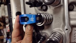
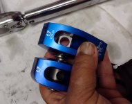
The "Blueprinting" part of the process is a combination of the machine work that gets done to proper specs, and the measuring of various clearances and specs including rod and main bearing clearances, crankshaft thrust, camshaft thrust, piston to wall clearance, ring gaps, deck height and lifter bore clearance, and don't forget rod side clearance. The cylinder heads, aside from needing to be machined properly, need valve spring pressure set up to go with the camshaft that is being used, and then pushrod length must be determined to work with the combination to achieve proper rocker arm geometry.
This particular pair of engines both had a breakage problem at almost the same time. They were Merc 454's with Pro Chargers on them, and they got run hard to get out of someone's way, and both broke one exhaust valve each. The owner asked about making more power, and since his blocks were not damaged we decided to bore them .030 to clean up, and use good forged internals to hold up to whatever boost he wanted to run. Parts availability and wait time are terrible right now, but I found a couple of Eagle forged 1pc rear main seal blocks to go with his Gen 5 blocks, along with some Eagle H beam rods. My go to source on pistons is Racetec, so I ordered a couple of sets of flat top pistons from them that would be just over 8.5-1 compression, good for what we are doing with the Prochargers. The pistons got made and sent directly to the balance shop in Long Beach, where I had already had all the other new parts for the rotating assemblies shipped.
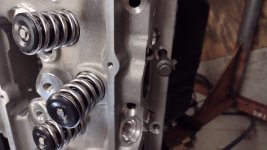
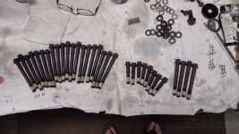
While waiting for pistons and balance, next trick was to track down some cylinder heads that would retain the stock exhaust port location so that modifications to the exhaust and/or transom would not be necessary to make it all fit. I decided some Brodix Race Rite heads would fill the bill and not completely break the bank, but no one really had them in stock, and the backorder list was long. I called Brodix direct to see if they knew of a dealer sitting on any stockpiles, and also got confirmation that the oval port heads would supply the necessary bottom end power, along with horsepower to meet our goals. They did sadly inform me that they can only produce a total of about 30 sets of heads per week due to the small foundry they use. I am pretty good at sourcing parts, and found some from another engine builder. He confirmed that he had made 600 hp with a single carb and small marine cam with a set, so I bought two sets from him, bare. Then I ordered good Ferrea severe duty intake valves and "Super Alloy" exhaust valves, which are said to handle temperature even better than Inconel valves. I've used them for years in forced induction engines after doing research, with no failures that I am aware of. Springs and cylinder head hardware all had to be purchased separately as well.
Next chore in these trying times was to locate a couple of suitable hydraulic roller cams. Many times I opt to run what's known as a "Sadi" cam core, they are cast and not as expensive as billet, but sadly no one really has them now. My normal custom cam grinder could not help, so I called an old contact at Iskenderian and was able to order two custom cams that Ron and I agreed would work with the Prochargers.
With most of the parts ordered, it was time to start the builds. Some people will assemble a block that was cleaned at the machine shop, but for a few reasons I do not. Once the blocks come back from the machine shop, I inspect them, then usually do a little grinding to remove sharp edges externally that would cut someone cleaning under or around them in the boat, and also take down some "flash" around oil drain backs and oil return passage from the oil filter. I also knock down the ridge in the rear main cap to help promote better flow. I have a selection of bristle brushes that I used to clean oil galleries, lifter bores and cylinder bores, and parts cleaning brushes to get all the rest of the block. I first will clean it with foaming engine degreaser that washes off with high pressure water after all areas are carefully brushed, and then I use a sprayer that I connect to my air compressor to spray it down with soapy water and again brush out all passages and bores. Then it gets washed off with a high pressure hose nozzle that fits into the oil galleries. I run it through both directions to be sure. Before starting to wash the block, I have some oil (I actually use ATF most of the time) to wipe down the cylinder walls, lifter bores and main saddles as soon as I dry them, since they flash rust pretty quickly in the desert environment that I live in.
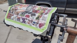
After the block is washed and allowed to dry I mask the block to paint and still allow a clean surface for gaskets. I cover the block with Duplicolor primer which is compatible to the Duplicolor engine enamel that I use. The paint has ceramic in it, and dries to a very nice shine that almost looks wet.


Once the masking materials are removed, one of the first things to do on a Gen 5/6 block is to put the 1/8" pipe plugs into the ports in the valley. Not a bad idea to put in the ones that are behind the cam gear now, but I usually have that in my routine later as two of those get drilled for timing chain oiling.

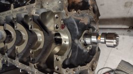
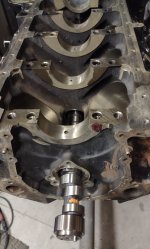
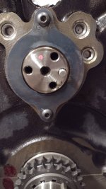
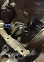
Next I usually install the cam bearings. I do that myself to insure they are put in carefully and correctly, and it also allows me to make sure the passages are very clean when I wash the block. The Gen 5/6 blocks use the same cam bearing set at as a MK IV block, but the oil holes must be positioned differently. Here I line them up from the front of the block and mark them with a sharpie. The alignment of the front one is more critical as there is only a single hole feeding the bearing. Numbers 2-4 have slots that allow more latitude in alignment, but I try to set them in similar positions. The rear main has a slot that circles the entire bearing. With a MK IV block I can verify the proper alignment of the oil hole in the bearing with a light, with the Gen 5/6 block I use a wire or a scribe with a 90 bend on the end to make sure the hole does get fed from the passage. I always wash the cam in the solvent tank, dry it and then test fit to make sure there is not an issue before proceeding. The Gen 5 blocks were originally flat tappet engines, but the blocks were machined to accept camshaft retaining plates that limit cam travel, or "thrust". Always a good idea to keep ignition timing stable as moving the cam will move the distributor. Cam thrust was measured at .003 on this engine. Also note in the photo that I have drilled the two 1/4" pipe plugs with .040" holes to help oil the timing chain. Oil serves two purposes in an engine, to lubricate and cool, so likely these oilers may extend the life of the timing chain.


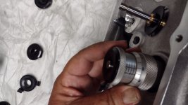
That stuff being done, it's time to measure bearing clearance. First I measure and record the crankshaft journal sizes on a piece of paper using a micrometer that reads down to .0001" (1/10,000"). Then the mic is set up carefully in a small vise so I can adjust a dial bore gauge to zero with the size of the journal. Main bearings of the correct type and size are set into the block and caps and torqued to the proper value. Then using the dial bore gauge the bearing clearance can be read and recorded. Normally the tightest point is at 90 degrees to the parting lines of the cap and block, but the dial bore gauge can be rotated to verify that fact. If the clearance is not what I am looking for (generally .0027" to .0032" for a big block Chevy), I can use different main bearings as they come in .001, .002 and X (extra clearance), including using two different shells that are .0005" different to get what I want. Many times a new crankshaft will be slightly on the "fat" side and require the extra clearance bearings. Once I am happy with the numbers, I use an electric engraver to mark the back of the shell so it can be cleaned in the solvent tank and go back to the same exact location.


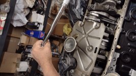
The same procedure follows for the connecting rod bearings. The rods get held in a special aluminum rod vise to prevent damage, and torque applied to the bolts with proper torque and lube as specified. In this case, 63 ft lbs with ARP lube. Bearings measured in the same fashion as the mains, looking for about .0025" to .003" clearance. .003" is the thickness of a sheet of normal paper, but of course we are splitting that in half and looking at about .0015" all the way around the crank.

Next in order is to fit the rings to the bores. I have an older Childs and Albert ring machine that has been serving me for a lot of years. I think there may be some better ones available now, but mine works great for me. Of course you can buy and use one of the less expensive hand crank manual ones as well, I still have one I started with before getting the electric one. Most sets of rings with come with what they suggest for minimum ring gap for varying types of usage. Marine usually means more than a street type gap, and forced induction even more yet. In this case using a .0055 multiplier supplied by the ring maker times the 4.280 bore, the result is .02345". Rounding up would give .024", but I added .001" to give a ring gap of .025". Remember, it's a minimum suggestion, and this is a heavy 32' boat these engines will go into. The rings get carefully put into the cylinder bore, then squared up with a tool designed to do that. Ring gap is checked with feeler gauges, I usually have two of them out when I am doing this to cover a range from smaller to my intended final gap. Any burrs are removed from the cut end of the ring with a small file or stone, then the rings need to get washed off in the solvent tank.


First, a bit of background on myself for those who are new or don’t have a clue who I am. I grew up around boats and boat racing, although my family never owned a boat. We got involved with the Pasadena Boat and Ski Club and went to various water ski and other boat racing events. Back then, one boat would serve as family boat, ski race boat, drag race boat and also run endurance races like the Parker 9 Hour. Through mutual friends, my dad met Lou Brummett who was building and racing the Mandella boats. The shop was close to our home so we spent quite a bit of time there, where I met Louis Unser, who was building Lou’s Ford race engines. Between those times and the shop and various water ski outings, my direction for the future was set. I would eventually get into water ski racing and engine building.
Before I start with all the details, a couple of quick notes about “Balance and Blueprint” To properly balance a rotating assembly for an engine, each combination of a piston, wrist pin, pin locks, connecting rod, connecting rod bearings and piston rings should weigh the same amount. Each of the 8 pistons for our V8 engine gets weighed and lighten to match to the lightest one in the group. Then each connecting rod is balanced, not just as a unit, but end for end. This is done by first hanging one end on a fixture and weighing the other. After the other end is matched, the rods get reversed and the opposite end is balanced. A combination of the piston, wrist pin, wrist pin locks, connecting rod, rings and rod bearings is calculated to make a "bob weight". The balance shop has brass weights that are clamped onto the crankshaft rod pins equal to the bob weight, and then the crank is spun on a machine that lets the operator know where to drill (or sometimes add) weight to make it perfectly balanced. Once the crank is in balance, the damper and flywheel/flexplate can be installed on the crank and spun as well to make sure they are perfect. That's the basic story about engine balancing, it will make the engine smooth.
The "Blueprinting" part of the process is a combination of the machine work that gets done to proper specs, and the measuring of various clearances and specs including rod and main bearing clearances, crankshaft thrust, camshaft thrust, piston to wall clearance, ring gaps, deck height and lifter bore clearance, and don't forget rod side clearance. The cylinder heads, aside from needing to be machined properly, need valve spring pressure set up to go with the camshaft that is being used, and then pushrod length must be determined to work with the combination to achieve proper rocker arm geometry.
This particular pair of engines both had a breakage problem at almost the same time. They were Merc 454's with Pro Chargers on them, and they got run hard to get out of someone's way, and both broke one exhaust valve each. The owner asked about making more power, and since his blocks were not damaged we decided to bore them .030 to clean up, and use good forged internals to hold up to whatever boost he wanted to run. Parts availability and wait time are terrible right now, but I found a couple of Eagle forged 1pc rear main seal blocks to go with his Gen 5 blocks, along with some Eagle H beam rods. My go to source on pistons is Racetec, so I ordered a couple of sets of flat top pistons from them that would be just over 8.5-1 compression, good for what we are doing with the Prochargers. The pistons got made and sent directly to the balance shop in Long Beach, where I had already had all the other new parts for the rotating assemblies shipped.
While waiting for pistons and balance, next trick was to track down some cylinder heads that would retain the stock exhaust port location so that modifications to the exhaust and/or transom would not be necessary to make it all fit. I decided some Brodix Race Rite heads would fill the bill and not completely break the bank, but no one really had them in stock, and the backorder list was long. I called Brodix direct to see if they knew of a dealer sitting on any stockpiles, and also got confirmation that the oval port heads would supply the necessary bottom end power, along with horsepower to meet our goals. They did sadly inform me that they can only produce a total of about 30 sets of heads per week due to the small foundry they use. I am pretty good at sourcing parts, and found some from another engine builder. He confirmed that he had made 600 hp with a single carb and small marine cam with a set, so I bought two sets from him, bare. Then I ordered good Ferrea severe duty intake valves and "Super Alloy" exhaust valves, which are said to handle temperature even better than Inconel valves. I've used them for years in forced induction engines after doing research, with no failures that I am aware of. Springs and cylinder head hardware all had to be purchased separately as well.
Next chore in these trying times was to locate a couple of suitable hydraulic roller cams. Many times I opt to run what's known as a "Sadi" cam core, they are cast and not as expensive as billet, but sadly no one really has them now. My normal custom cam grinder could not help, so I called an old contact at Iskenderian and was able to order two custom cams that Ron and I agreed would work with the Prochargers.
With most of the parts ordered, it was time to start the builds. Some people will assemble a block that was cleaned at the machine shop, but for a few reasons I do not. Once the blocks come back from the machine shop, I inspect them, then usually do a little grinding to remove sharp edges externally that would cut someone cleaning under or around them in the boat, and also take down some "flash" around oil drain backs and oil return passage from the oil filter. I also knock down the ridge in the rear main cap to help promote better flow. I have a selection of bristle brushes that I used to clean oil galleries, lifter bores and cylinder bores, and parts cleaning brushes to get all the rest of the block. I first will clean it with foaming engine degreaser that washes off with high pressure water after all areas are carefully brushed, and then I use a sprayer that I connect to my air compressor to spray it down with soapy water and again brush out all passages and bores. Then it gets washed off with a high pressure hose nozzle that fits into the oil galleries. I run it through both directions to be sure. Before starting to wash the block, I have some oil (I actually use ATF most of the time) to wipe down the cylinder walls, lifter bores and main saddles as soon as I dry them, since they flash rust pretty quickly in the desert environment that I live in.
After the block is washed and allowed to dry I mask the block to paint and still allow a clean surface for gaskets. I cover the block with Duplicolor primer which is compatible to the Duplicolor engine enamel that I use. The paint has ceramic in it, and dries to a very nice shine that almost looks wet.
Once the masking materials are removed, one of the first things to do on a Gen 5/6 block is to put the 1/8" pipe plugs into the ports in the valley. Not a bad idea to put in the ones that are behind the cam gear now, but I usually have that in my routine later as two of those get drilled for timing chain oiling.
Next I usually install the cam bearings. I do that myself to insure they are put in carefully and correctly, and it also allows me to make sure the passages are very clean when I wash the block. The Gen 5/6 blocks use the same cam bearing set at as a MK IV block, but the oil holes must be positioned differently. Here I line them up from the front of the block and mark them with a sharpie. The alignment of the front one is more critical as there is only a single hole feeding the bearing. Numbers 2-4 have slots that allow more latitude in alignment, but I try to set them in similar positions. The rear main has a slot that circles the entire bearing. With a MK IV block I can verify the proper alignment of the oil hole in the bearing with a light, with the Gen 5/6 block I use a wire or a scribe with a 90 bend on the end to make sure the hole does get fed from the passage. I always wash the cam in the solvent tank, dry it and then test fit to make sure there is not an issue before proceeding. The Gen 5 blocks were originally flat tappet engines, but the blocks were machined to accept camshaft retaining plates that limit cam travel, or "thrust". Always a good idea to keep ignition timing stable as moving the cam will move the distributor. Cam thrust was measured at .003 on this engine. Also note in the photo that I have drilled the two 1/4" pipe plugs with .040" holes to help oil the timing chain. Oil serves two purposes in an engine, to lubricate and cool, so likely these oilers may extend the life of the timing chain.
That stuff being done, it's time to measure bearing clearance. First I measure and record the crankshaft journal sizes on a piece of paper using a micrometer that reads down to .0001" (1/10,000"). Then the mic is set up carefully in a small vise so I can adjust a dial bore gauge to zero with the size of the journal. Main bearings of the correct type and size are set into the block and caps and torqued to the proper value. Then using the dial bore gauge the bearing clearance can be read and recorded. Normally the tightest point is at 90 degrees to the parting lines of the cap and block, but the dial bore gauge can be rotated to verify that fact. If the clearance is not what I am looking for (generally .0027" to .0032" for a big block Chevy), I can use different main bearings as they come in .001, .002 and X (extra clearance), including using two different shells that are .0005" different to get what I want. Many times a new crankshaft will be slightly on the "fat" side and require the extra clearance bearings. Once I am happy with the numbers, I use an electric engraver to mark the back of the shell so it can be cleaned in the solvent tank and go back to the same exact location.
The same procedure follows for the connecting rod bearings. The rods get held in a special aluminum rod vise to prevent damage, and torque applied to the bolts with proper torque and lube as specified. In this case, 63 ft lbs with ARP lube. Bearings measured in the same fashion as the mains, looking for about .0025" to .003" clearance. .003" is the thickness of a sheet of normal paper, but of course we are splitting that in half and looking at about .0015" all the way around the crank.
Next in order is to fit the rings to the bores. I have an older Childs and Albert ring machine that has been serving me for a lot of years. I think there may be some better ones available now, but mine works great for me. Of course you can buy and use one of the less expensive hand crank manual ones as well, I still have one I started with before getting the electric one. Most sets of rings with come with what they suggest for minimum ring gap for varying types of usage. Marine usually means more than a street type gap, and forced induction even more yet. In this case using a .0055 multiplier supplied by the ring maker times the 4.280 bore, the result is .02345". Rounding up would give .024", but I added .001" to give a ring gap of .025". Remember, it's a minimum suggestion, and this is a heavy 32' boat these engines will go into. The rings get carefully put into the cylinder bore, then squared up with a tool designed to do that. Ring gap is checked with feeler gauges, I usually have two of them out when I am doing this to cover a range from smaller to my intended final gap. Any burrs are removed from the cut end of the ring with a small file or stone, then the rings need to get washed off in the solvent tank.
Attachments
Last edited:


