WELCOME TO RIVER DAVES PLACE

Main Bearings Good Bad Or Ugly?

RiverJeff

Well-Known Member
Joined
Sep 21, 2016
Messages
49
Reaction score
51
Alright guys interesting think tank session.

Im tearing down my 572 BBC with the intention to increase compression from 9.8:1 flat top pistons to 11.25 or 11.5:1 domes. This also gives me the opportunity to check out the health of the motor I built in 2019.

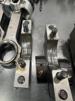
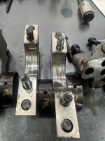
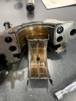
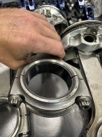
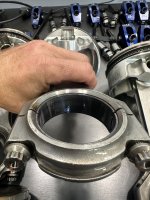
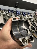
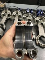
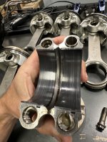
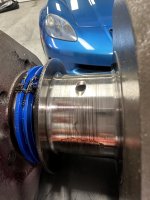
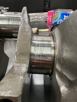
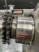
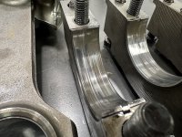
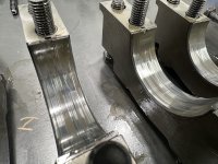
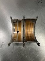
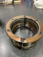
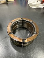
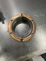
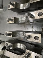
Question for the group. The rod bearings look brand new (see pics). But the main bearings look to me like they have accelerated wear. It’s consistent across the mains, no major debris, no side load, but worn past the babbet.

What do you think? First is it a problem? If it is what caused it? I’ll check clearances next. The confusion for me is the rods (priority main block) look brand new!


Max (dog), my garage intern didn’t do the bearing check so don’t blame him…
 

Attachments

  • IMG_5769.jpeg
    IMG_5769.jpeg
    1.3 MB · Views: 178
  • IMG_5772.mov
    1.8 MB
  • IMG_5766.jpeg
    IMG_5766.jpeg
    2 MB · Views: 179
  • IMG_5767.jpeg
    IMG_5767.jpeg
    1.7 MB · Views: 187
  • IMG_5768.jpeg
    IMG_5768.jpeg
    1.8 MB · Views: 175
  • IMG_5771.jpeg
    IMG_5771.jpeg
    1.9 MB · Views: 174
  • IMG_5770.jpeg
    IMG_5770.jpeg
    1.5 MB · Views: 168

obnoxious001

Engine building character
Joined
Dec 28, 2007
Messages
6,636
Reaction score
4,144
Rear main is destroyed, which of course sends material through the rest of the engine. Photos of the rod bearings are not clear enough for me to say for sure.

Please shoot photos of the thrust surfaces on the rear main bearings. Pair them together and show me both sides.
 

RiverJeff

Well-Known Member
Joined
Sep 21, 2016
Messages
49
Reaction score
51
You guys are quick! Got me diggin more which is great.

Here’s pics of the thrust bearing, mains, and rods.

Not to create a spoiler alert but this got me deeper into the build.

History: this motor had an oil issue and spun main & rod bearings. It was communicated the journals for mains and rods were ground 20 under. The bearings in there now are 0.020” oversized main and rod.

I just threw a caliper on the journals and I’m getting .010 under rod journals and .005 under mains.

With .020 bearings could we be looking at “self clearanced” mains?
 

Attachments

  • IMG_5785.jpeg
    IMG_5785.jpeg
    1.5 MB · Views: 107
  • IMG_5786.jpeg
    IMG_5786.jpeg
    1.6 MB · Views: 106
  • IMG_5787.jpeg
    IMG_5787.jpeg
    1.6 MB · Views: 107
  • IMG_5793.jpeg
    IMG_5793.jpeg
    1.4 MB · Views: 100
  • IMG_5796.jpeg
    IMG_5796.jpeg
    1.7 MB · Views: 106
  • IMG_5797.jpeg
    IMG_5797.jpeg
    1.8 MB · Views: 108
  • IMG_5781.jpeg
    IMG_5781.jpeg
    2.1 MB · Views: 107
  • IMG_5782.jpeg
    IMG_5782.jpeg
    1.8 MB · Views: 99
  • IMG_5783.jpeg
    IMG_5783.jpeg
    1.7 MB · Views: 93
  • IMG_5775.jpeg
    IMG_5775.jpeg
    2.2 MB · Views: 107
  • IMG_5776.jpeg
    IMG_5776.jpeg
    1.8 MB · Views: 97
  • IMG_5779.jpeg
    IMG_5779.jpeg
    1.7 MB · Views: 99
  • IMG_5777.jpeg
    IMG_5777.jpeg
    1.8 MB · Views: 97
  • IMG_5778.jpeg
    IMG_5778.jpeg
    2.2 MB · Views: 101
  • IMG_5780.jpeg
    IMG_5780.jpeg
    1.9 MB · Views: 97

obnoxious001

Engine building character
Joined
Dec 28, 2007
Messages
6,636
Reaction score
4,144
No such thing as a .005 under main, unless it's been ground away by grit in the engine, are you sure you are reading the mic correctly? Or, are you measuring a damaged journal? .020" bearings would not let a .010" crank spin, it would lock up when the main bolts were torqued. What number are you getting for the mains? Are the rod bearings .010"? I didn't see a photo of the back of them?

Crank thrust appears to be damaged. That could have started the problem assuming clearances were anywhere close to being correct. How much crank thrust did you measure when you put it together? It's been a long weekend, not trusting myself looking at these photos since one click of the enlarge button makes them huge, no in between, and I am looking on a 50" screen.

Where are you located? No one out here by me grinding cranks, but there are some places in So Cal.
 

obnoxious001

Engine building character
Joined
Dec 28, 2007
Messages
6,636
Reaction score
4,144
You guys are quick! Got me diggin more which is great.

Here’s pics of the thrust bearing, mains, and rods.

Not to create a spoiler alert but this got me deeper into the build.

History: this motor had an oil issue and spun main & rod bearings. It was communicated the journals for mains and rods were ground 20 under. The bearings in there now are 0.020” oversized main and rod.

I just threw a caliper on the journals and I’m getting .010 under rod journals and .005 under mains.

With .020 bearings could we be looking at “self clearanced” mains?
Calipers are only valid for a rough measurement on the crank. Your mains are chewed up so you can only get a rough measurement anyway. By the way, the rod bearings are definitely not looking "brand new", debris has run through them as well.

Who did the measuring and assembly?
 

RiverJeff

Well-Known Member
Joined
Sep 21, 2016
Messages
49
Reaction score
51
Agreed on the calipers verity in measurement. I’ll get the Mic’s on them next.

I’m in So Cal.

Good point on the 0.020” (or .015” small) wouldn’t let the crank spin once torqued. I’ll get a better measurement to confirm.

In there now are 0.020” oversized bearings both rod and main.

The question is where are the journals relative to the bore size (main & rod). Rods didn’t have excess wear (yes some gouges but I’m also not building in a clean room so maybe that lost piece of sand I was looking for).

Mains obviously had a problem. Sounds like we’re in agreement that it’s a set up problem not oil pressure. I’ll confirm all the measurements next. Pfaff Bacca Marine helped with the set up, I’ll give them a call too, to see if they can help.
 

RiverJeff

Well-Known Member
Joined
Sep 21, 2016
Messages
49
Reaction score
51
Okay internet you guys were right. I pulled out the mic’s and the journals are .020” under so correct bearings.

Where would you look next? If it was an oil pressure issue wouldn’t rod bearings look this bad too?
IMG_5802.jpeg
 

HST4ME

Well-Known Member
Joined
Nov 9, 2015
Messages
7,464
Reaction score
17,330
When the crank was ground the radius on the journal probably wasn't held correctly and/or the thrust surface was opened up.
 

Bajastu

Well-Known Member
Joined
Oct 10, 2017
Messages
972
Reaction score
2,295
By tearing it down now, you just saved yourself from a catastrophic failure. I too say your end play was way off and it roasted the thrust. The material made its way through the rest of the engine and started the downward spiral on the rest of the bearings and components. My vote would be improper crank grind.

At .020 on the crank, I’d say it’s time to replace it.
 

Malibuvride07

Well-Known Member
Joined
Sep 2, 2012
Messages
86
Reaction score
173
For what it’s worth our almost 17:1 alcohol motor in my modified would use up mains way sooner than rods. For us the biggest issue had to deal with methanol wash down creating lower pressure before the motor made heat and burned the alcohol out. Dad used to trip out cause as a driver I could tell him when mains were needed before it tore up the motor. Saved all but two motors throughout 9 years of racing that way 😂.
Now not likely your cause at that low a compression but just a statistic as to how mains can wear fast than rods. But the real motor guys on here already gave some clues as to look for and appears you’ll be looking for a new crank. Good luck with your build.
 

obnoxious001

Engine building character
Joined
Dec 28, 2007
Messages
6,636
Reaction score
4,144
Where would you look next? View attachment 1346397
I suggest you go back up and read a couple of my posts where I asked who did the measuring, and how much crank thrust there was at assembly. Then look and see if something was jammed up in the driveline. It takes very little pressure to push the crank against the thrust bearing and cut off oil to that side of the thrust surface, which will end up destroying the bearing. I have a couple of bearings I saved that both had known thrust issues.
 

Bajastu

Well-Known Member
Joined
Oct 10, 2017
Messages
972
Reaction score
2,295
One question; what’s the drive propulsion, JET, V-drive, or I/O ? Just curious if it’s a V-drive with a trans or a velvet drive.
 

obnoxious001

Engine building character
Joined
Dec 28, 2007
Messages
6,636
Reaction score
4,144
One question; what’s the drive propulsion, JET, V-drive, or I/O ? Just curious if it’s a V-drive with a trans or a velvet drive.
I think any of them might take out a thrust bearing under the right circumstances, that's what I was sort of leaning towards. Other thing is, was the correct .005-.007" thrust set up during assembly, no answer on that yet.
 

RiverJeff

Well-Known Member
Joined
Sep 21, 2016
Messages
49
Reaction score
51
I think any of them might take out a thrust bearing under the right circumstances, that's what I was sort of leaning towards. Other thing is, was the correct .005-.007" thrust set up during assembly, no answer on that yet.

Appreciate the good feedback guys. This is in a jet 21' Daytona.

I set up the mains back in 2019. The thrust would have been set to spec, actually I think that's why the front thrust bearing surface is ground down a bit to set up correctly.

I went on a deep dive into my records for more history on this motor set up. I was having an oil pressure issue early on from a Milodon pan that allowed the oil to get whipped up and aerate. I switched to a Dan Olson pan which solved the issue but not until I had a season on the other pan.

Im wondering now if the aerated low oil pressure coupled with a season of run time could have wiped out the mains, then new pan solved the oil pressure, but damage done on the bearings.
 

Attachments

  • IMG_5225.jpeg
    IMG_5225.jpeg
    1.5 MB · Views: 44

poncho

Well-Known Member
Joined
Dec 20, 2007
Messages
6,195
Reaction score
11,101
Appreciate the good feedback guys. This is in a jet 21' Daytona.

I set up the mains back in 2019. The thrust would have been set to spec, actually I think that's why the front thrust bearing surface is ground down a bit to set up correctly.

I went on a deep dive into my records for more history on this motor set up. I was having an oil pressure issue early on from a Milodon pan that allowed the oil to get whipped up and aerate. I switched to a Dan Olson pan which solved the issue but not until I had a season on the other pan.

Im wondering now if the aerated low oil pressure coupled with a season of run time could have wiped out the mains, then new pan solved the oil pressure, but damage done on the bearings.
The guy's here know way more than me but this subject came up this morning on FB. I have the Milodon pan and when I built my stroker motor I didn't realize I needed to take a quart of oil out for the longer crank throw. Luckily it was one run down a lake and I dropped to idle and saw my oil pressure drop to 10 pounds.
I was thinking heat related so I drifted 10-15 minutes before I restarted it, oil pressure was back.
For some reason that pan is called 10 quarts and really should be filled with 9 quarts and 8 with a stroker.
 

RiverJeff

Well-Known Member
Joined
Sep 21, 2016
Messages
49
Reaction score
51
The guy's here know way more than me but this subject came up this morning on FB. I have the Milodon pan and when I built my stroker motor I didn't realize I needed to take a quart of oil out for the longer crank throw. Luckily it was one run down a lake and I dropped to idle and saw my oil pressure drop to 10 pounds.
I was thinking heat related so I drifted 10-15 minutes before I restarted it, oil pressure was back.
For some reason that pan is called 10 quarts and really should be filled with 9 quarts and 8 with a stroker.

Oh trust me I about got committed to an insane asylum over this. More oil, less oil, different weights .... I could never get this pan to work with my set up. that 4.500" stroke was just too much. It's now living happily in a different 496 build and has never had issues in that with 4.250" stroke.
 

obnoxious001

Engine building character
Joined
Dec 28, 2007
Messages
6,636
Reaction score
4,144
Appreciate the good feedback guys. This is in a jet 21' Daytona.

I set up the mains back in 2019. The thrust would have been set to spec, actually I think that's why the front thrust bearing surface is ground down a bit to set up correctly.

I went on a deep dive into my records for more history on this motor set up. I was having an oil pressure issue early on from a Milodon pan that allowed the oil to get whipped up and aerate. I switched to a Dan Olson pan which solved the issue but not until I had a season on the other pan.

Im wondering now if the aerated low oil pressure coupled with a season of run time could have wiped out the mains, then new pan solved the oil pressure, but damage done on the bearings.
Is there a windage tray under the oil in the pan in that photo? Level needs to be set so oil does not sit on top of the tray.

Some of the Milodon pickups use a perforated metal instead of actual screen. I don't like that type pickup and would usually use something else that allows more flow.
 

lbhsbz

Putting on the brakes
Joined
Jan 11, 2010
Messages
13,601
Reaction score
35,685
2 things...

1: Do you have sufficient slip yoke clearance on your driveline? I set mine up pretty tight one time (about .030") and with hull flex, the pump was leaning on the back on the back of the crank and wiped out the thrust surface and bearings

2: While not really visable in the bearing wear, I'd bolt the main caps back on with no bearings and bore gauge them towards the rear and the front of each main bore. I've had one that was line honed, and the shop failed to properly clean things before torquing the caps down, which resulted in the rear main cap being sitting at an angle when it was honed, consequently I had about 0.007" of clearance at the rear of the rear main bearing and about 0.002" at the front....but about 0.004" right in the middle where I originally checked it, which I was happy with.

I'd also throw the crank on some V-blocks (you can make some out of scrap plywood with a jigsaw) and measure radial runout on the 3 center main journals....see if it's bent.
 

RiverJeff

Well-Known Member
Joined
Sep 21, 2016
Messages
49
Reaction score
51
I’m back and with some answers!

Took the motor down to the block and brought the rotating assembly to my machine shop for some detective work. After reviewing the current set up and build history I think we found the culprit… damn owner messing things up!

In 2016 I spun a main, apparently these need proper oil flow, ‘don’t cross the streams’ ie oil cooler lines. The machine shop then ground the crank .020 under on mains .010 on rods also main line bore/hone .005. They set up the main bearings in 2016 with half shells for proper clearance (foreshadowing).

Engine ran but I had a consistent oil pressure issue at high RPM. In 2019 I solved this to be the Milodon oil pan not having enough windage protection. In 2019 changed to Dan Olsen (great ever since). But at that time had excessive main bearing wear caused by the low pressure with RPM. So when the pan was swapped so too were the main bearings. Still 0.020 undersized but I was unaware of the half shells.

Fast forward to 2024. I’m rebuilding this 572 to increase power and find the mains are shot! Turns out not enough clearance due to “standard” 0.020 undersized main bearing install back in 2019.

So Sherlock, we’ve solved the mystery! (Hopefully)

Now for the fun.

Crank was re-polished, machine shop set up mains and rod clearances (I verified with mics), cylinders honed, ready for new stuff.

Build list:
AFR 385cc CNC heads
RaceTech custom 11.4cc dome
Final compression 10.38:1
Bill Mitchell Racing intake
Quickfuel 1150 dominator carb
Isky Solid cam 668/671 lift
A/B impeller

Build started this week… stay tuned hope to get a few runs in this year!


IMG_1073.jpeg
IMG_1071.jpeg
IMG_1075.jpeg
IMG_1072.jpeg
IMG_1631.jpeg
IMG_1642.jpeg
IMG_1643.jpeg
IMG_1644.jpeg
IMG_1675.jpeg

IMG_1696.jpeg
IMG_1700.jpeg
IMG_1711.jpeg
IMG_1709.jpeg
IMG_1710.jpeg
IMG_1713.jpeg
IMG_1714.jpeg
IMG_1715.jpeg
 

mattyc

Well-Known Member
Joined
Sep 9, 2017
Messages
504
Reaction score
620
I’m back and with some answers!

Took the motor down to the block and brought the rotating assembly to my machine shop for some detective work. After reviewing the current set up and build history I think we found the culprit… damn owner messing things up!

In 2016 I spun a main, apparently these need proper oil flow, ‘don’t cross the streams’ ie oil cooler lines. The machine shop then ground the crank .020 under on mains .010 on rods also main line bore/hone .005. They set up the main bearings in 2016 with half shells for proper clearance (foreshadowing).

Engine ran but I had a consistent oil pressure issue at high RPM. In 2019 I solved this to be the Milodon oil pan not having enough windage protection. In 2019 changed to Dan Olsen (great ever since). But at that time had excessive main bearing wear caused by the low pressure with RPM. So when the pan was swapped so too were the main bearings. Still 0.020 undersized but I was unaware of the half shells.

Fast forward to 2024. I’m rebuilding this 572 to increase power and find the mains are shot! Turns out not enough clearance due to “standard” 0.020 undersized main bearing install back in 2019.

So Sherlock, we’ve solved the mystery! (Hopefully)

Now for the fun.

Crank was re-polished, machine shop set up mains and rod clearances (I verified with mics), cylinders honed, ready for new stuff.

Build list:
AFR 385cc CNC heads
RaceTech custom 11.4cc dome
Final compression 10.38:1
Bill Mitchell Racing intake
Quickfuel 1150 dominator carb
Isky Solid cam 668/671 lift
A/B impeller

Build started this week… stay tuned hope to get a few runs in this year!


View attachment 1416926 View attachment 1416927 View attachment 1416928 View attachment 1416929 View attachment 1416930 View attachment 1416931 View attachment 1416932 View attachment 1416933 View attachment 1416934
View attachment 1416935 View attachment 1416936 View attachment 1416937 View attachment 1416938 View attachment 1416939 View attachment 1416940 View attachment 1416941 View attachment 1416942 View attachment 1416943
Looking good! Nice job getting to the bottom of your main bearing problem, good documentation goes a long way
 

RiverJeff

Well-Known Member
Joined
Sep 21, 2016
Messages
49
Reaction score
51
With the motor going back together I’ll turn this a bit more into a build thread.

Cam timing question for you guys. Isky solid roller card attached. This is a custom grind from them set up for a 21’ Daytona with an A/B impeller max rpm 6,500.

That was made for the last build, flat top lower 9.0:1 compression and iron heads. Hoping for a bit more power with new heads and dome pistons 10.38:1 compression.

I’ve degreed the cam straight up (dot to dot) and it matches the cam card.

The question is do I advance, retard, or leave it from here?

If we’re going to make more power but same limit on the A/B impeller does it make sense to advance the cam to shift the power curve down a couple hundred rpm? I have no experience with this and am leaning toward listening to ISKY with their initial advice to set straight up. Anyone play with this?
 

Attachments

  • IMG_3237.jpeg
    IMG_3237.jpeg
    1.3 MB · Views: 0

mattyc

Well-Known Member
Joined
Sep 9, 2017
Messages
504
Reaction score
620
With the motor going back together I’ll turn this a bit more into a build thread.

Cam timing question for you guys. Isky solid roller card attached. This is a custom grind from them set up for a 21’ Daytona with an A/B impeller max rpm 6,500.

That was made for the last build, flat top lower 9.0:1 compression and iron heads. Hoping for a bit more power with new heads and dome pistons 10.38:1 compression.

I’ve degreed the cam straight up (dot to dot) and it matches the cam card.

The question is do I advance, retard, or leave it from here?

If we’re going to make more power but same limit on the A/B impeller does it make sense to advance the cam to shift the power curve down a couple hundred rpm? I have no experience with this and am leaning toward listening to ISKY with their initial advice to set straight up. Anyone play with this?
I'm no expert here, but advancing the cam is going to increase cylinder pressures. You're increasing cylinder pressure already with the increase in static compression. Are you planning on running pump gas? I would think leaving it straight up would be the better option. Hopefully someone can confirm or deny this.
 

obnoxious001

Engine building character
Joined
Dec 28, 2007
Messages
6,636
Reaction score
4,144
With the motor going back together I’ll turn this a bit more into a build thread.

Cam timing question for you guys. Isky solid roller card attached. This is a custom grind from them set up for a 21’ Daytona with an A/B impeller max rpm 6,500.

That was made for the last build, flat top lower 9.0:1 compression and iron heads. Hoping for a bit more power with new heads and dome pistons 10.38:1 compression.

I’ve degreed the cam straight up (dot to dot) and it matches the cam card.

The question is do I advance, retard, or leave it from here?

If we’re going to make more power but same limit on the A/B impeller does it make sense to advance the cam to shift the power curve down a couple hundred rpm? I have no experience with this and am leaning toward listening to ISKY with their initial advice to set straight up. Anyone play with this?
I've dealt with Iskenderian quite a bit, ranging from a long time ago and starting up again the past couple of years when my small shop cam grinder friend was not able to buy roller blanks. That being said, I would probably follow their advice, but unfortunately this year we lost Ron Iskenderian whose personal cell phone number I had when I wanted to check something.

Normally speaking with most camshafts I will advance the cam at least two degrees to allow for timing chain stretch. Advancing the cam does move the power band down.
 

RiverJeff

Well-Known Member
Joined
Sep 21, 2016
Messages
49
Reaction score
51
Well decided to trust the pros at Isky and set up dot to dot. May mess with impeller size and cam combo down the road depending on performance.

Here’s some of the shots going together.

Now, who knows a good place So Cal adjacent to run on a dyno without breaking the bank?


IMG_1780.jpeg
IMG_1827.jpeg
IMG_1829.jpeg
IMG_1832.jpeg
IMG_1834.jpeg
IMG_1835.jpeg
IMG_1838.jpeg
IMG_1841.jpeg
IMG_1843.jpeg
IMG_1845.jpeg
IMG_1851.jpeg
IMG_1854.jpeg
IMG_1855.jpeg
IMG_1856.jpeg
IMG_1860.jpeg
IMG_1862.jpeg
IMG_1864.jpeg
 

RiverJeff

Well-Known Member
Joined
Sep 21, 2016
Messages
49
Reaction score
51
Are those AFR 315's? Lookin' good!
Thanks!! AFR 385cc went for the big dogs!

Definitely not maxed out with the current cam. Spoke with ISKY on that and the limiter is the A/B impeller. Bench racing the idea of swapping the impeller in the future and increasing the cam size to maximize the head flow. For now see how much power we have with the current cam...
 

28Eliminator

Well-Known Member
Joined
Feb 10, 2011
Messages
11,540
Reaction score
11,862
Thanks!! AFR 385cc went for the big dogs!

Definitely not maxed out with the current cam. Spoke with ISKY on that and the limiter is the A/B impeller. Bench racing the idea of swapping the impeller in the future and increasing the cam size to maximize the head flow. For now see how much power we have with the current cam...

That seems like an awful big Port for a 6500rpm N/A engine? have you tried this combo before?
 

Rennsport

Well-Known Member
Joined
May 26, 2024
Messages
237
Reaction score
638
With respect to dyno services consider Randy Aase at Aasco in Anaheim. Super guy!
 
Top