Toolman
Well-Known Member
- Joined
- Aug 19, 2014
- Messages
- 481
- Reaction score
- 776


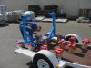
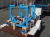
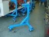
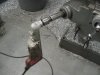
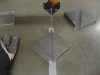
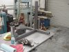
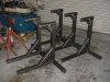
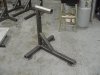
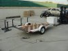
Turning a roller valve train by the front of the crankshaft, could create a problem when you have only one foot holding up the front motor half, and you are trying to rotate it . I use a motor stand that has two bottom wheels at the front, along with 2 at the back . I want the stand to be strong and balanced enough to 'torque the bolts' along with being able to run the motor on the stand . Please re-invent your design before you take it to market . PS, where is the oil drip pan on your design ?
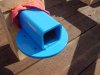
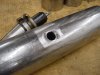
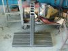
Hey guy, It's not my design and it's not for a car engine. It's areospace. I can't show you what goes in the top tube. But basically, it's just a engine stand on 'roids. But yes, 4 points are better than 3 for V-8's.
.jpg")
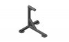
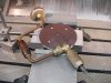
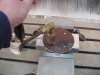
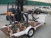
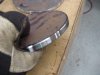
If they need a matching engine leveler keep me in mind.... View attachment 385944
")
Nice piece there Roger 1
Hey guy, It's not my design and it's not for a car engine. It's areospace. I can't show you what goes in the top tube. But basically, it's just a engine stand on 'roids. But yes, 4 points are better than 3 for V-8's.
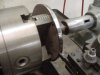
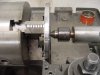
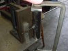
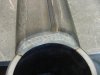
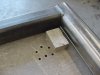
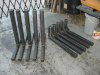
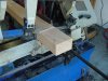
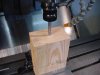
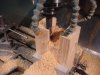
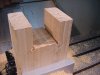
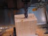
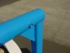
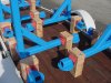
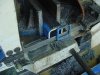
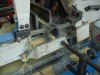
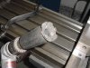
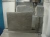
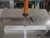
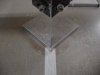
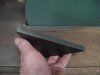
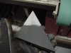
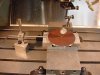
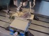
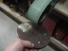
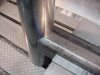
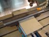
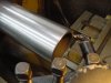
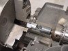
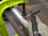
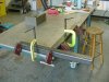
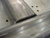
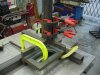
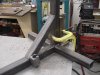
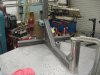
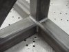
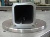
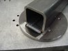
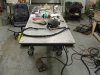
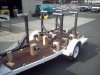
Simple set-up using the square sides of the jig table.
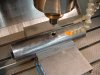
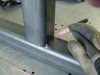
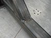
Tack tubes on oppisite corners.
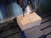
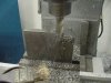
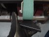
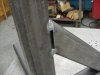
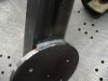
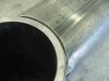
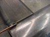
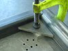
Weld towards the tack using 3/32 rod and a 1/8 tungsten. Starting at the tack could melt it and the tube will move.
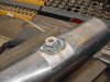
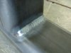
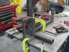
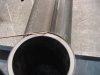
Then I use 1/8 rod to fill the major gap'osis.
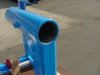
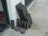
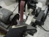
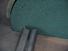
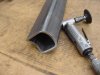
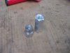
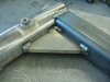
What do you notch round tube with? Tired of my HF notcher.

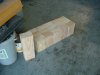
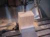
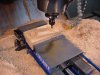
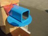
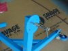
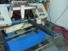
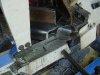
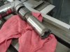
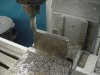
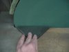
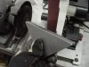
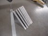
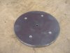
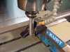
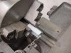
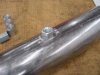
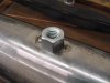
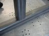
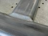
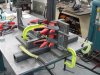
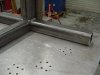
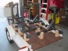
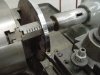
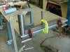
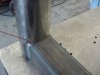
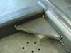
So I'm just goofing around in the shop and I happen to glance over at the last stand I tacked up which was still on the table. Notice anything wrong with the 2nd pic? I'm sooooooo glad I saw it before I started putting on the angle brace. It was only one stand.
You started with the ' cheap engine stand reference', and I kindly pointed out a few items to consider. (just consider) Then you come back with your 'hey guy shit' , OK we don't know each other, but you should have checked out that I'm one of the GUYS around here who could be a good customer for your work . I'm no big deal but isn't showing your work here just a 'sales pitch' ? You have not come here to be 'educational' in the past, will that change ? I posted a 'make some more shaft and rudder extended lube kits' and you never contacted me about purchasing anything . For me it's 'way easier to give you my wrath, than give you my cash", what's better for you ? Hey, up front . If you were actually all about 'the aerospace contracts', you would not be spamming for 'simple boat parts' here . I mean no disrespect, but I don't shit where I expect to eat at some time .
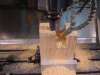
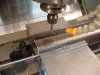
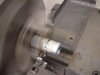
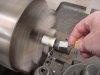
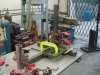
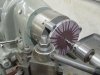
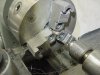
For reals?
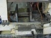
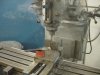
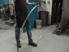
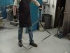
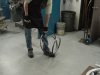
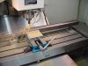
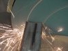
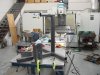
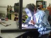
You know they have power feeds for the knee, right?
That "knee power feed" just looks like a whole bunch of puckering to me.
I'm not sure what's going on here, but to get directly to the point I don't care.
The entire purpose of this section of the board is to post threads like this. To show how things are made, and that novices might learn something from it, and experts might learn a different way of doing it. I myself looked at some of the ways things were being done, and thought "I'd do that different?" but at the same time learned another way to do something that I didn't know before.
Stop being so negative guys. It isn't necessary nor is it productive.
RD
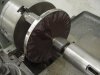
I didn't say it to be negative. Honestly, it looked downright dangerous to me. I've never tried it. Servo makes power feeds to mount directly on the machine. My knee mill has one.
I imagined the torque it would take to raise the knee would make it difficult to hold onto a drill.
I have posted positive comments on toolmans projects in the past. I'll refrain from commenting in the future.
My apologies to toolman if it came off as a slam.
Brian
What do you notch round tube with? Tired of my HF notcher.
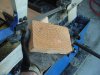
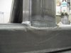
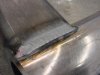
. . . and beautiful looking welds there, mine look like someone squeezed them into place with a tube of toothpaste.
I didn't say it to be negative. Honestly, it looked downright dangerous to me. I've never tried it. "Servo" makes power feeds to mount directly on the machine. My knee mill has one.
I imagined the torque it would take to raise the knee would make it difficult to hold onto a drill.
I have posted positive comments and gave "thanks" on toolmans projects in the past. I'll refrain from commenting in the future.
My apologies to toolman if it came off as a slam.
Brian