WELCOME TO RIVER DAVES PLACE

Back on it

slowride

Well-Known Member
Joined
Dec 19, 2007
Messages
1,357
Reaction score
484
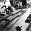
After some diversions, I'm getting my life back on track. On the back burner for far too long was getting the frame welded up so I can get it rolling. A conventional frame rack would take up too much room, so I had an idea. I sunk studs in the slab and made up brackets to hold the frame in position and reduce twist while welding. Don't know if it's been done before, but as long as I'm determined to do EVERYTHING on this car, might as well try it out.
It'll be tied down in 8 places and supported with the leveling jacks making it easy to level and keep the frame square. At least that's the plan.......
 

Attachments

  • fr-rack.jpg
    fr-rack.jpg
    74.9 KB · Views: 82

DLow

Single Barrel Dweller
Joined
Jun 28, 2012
Messages
3,788
Reaction score
5,782
I think that's a pretty cool idea. As long as those tie down straps don't get in the way too much, you're golden. Could always weld a temp bolt to bottom of frame to attach to if necessary. Show some more pics of your progress.
 

slowride

Well-Known Member
Joined
Dec 19, 2007
Messages
1,357
Reaction score
484
I think that's a pretty cool idea. As long as those tie down straps don't get in the way too much, you're golden. Could always weld a temp bolt to bottom of frame to attach to if necessary. Show some more pics of your progress.

Shouldn't be a problem. I made the brackets wide enough to clear the boxing plates when I start tacking them in place.
 

slowride

Well-Known Member
Joined
Dec 19, 2007
Messages
1,357
Reaction score
484
Minor update. The shop is cleaned up and getting my focus back.
Spacers are going in inside the boxed rail to reduce flex at the motor mounts and the rear running board brackets. This will be full fendered and street driven so every little trick I can incorporate to strengthen the rails is time well spent.
First pic shows the "spacer"..... 1-3/4" DOM tube scraps tacked in the rail
2nd pic is a close up.... nothing fancy needed
Last pic shows how it ties together with the front ladder bar pivot. Should keep the rail from rolling over at the running board bracket and effectively triangulating the ladder pivots.
frm1.jpg frm2.jpg frm3.jpg
 

slowride

Well-Known Member
Joined
Dec 19, 2007
Messages
1,357
Reaction score
484
To make the spacers rock solid, I've drilled holes in the boxing plates to plug weld them to the plates. been a lot of filling holes, tacking nuts inside the rails and fitting the tube the past week. Should have it boxed and ready to test fit the engine and trans next weekend.
plug1.jpg plug2.jpg
 

Toolman

Well-Known Member
Joined
Aug 19, 2014
Messages
456
Reaction score
701
We did a lot of Legend Car racing here at our shop. And I've welded a lot of frames. Just be sure you make the welds work against each other. Weld an inch on one side of the car, then go to opposite side of the car and weld an inch in the exact same place. Don't go all the way down one side of the car, then all the way down the other. It's more work, but it works. Welds shrink as they cool, and so they pull hard. Hope this helps. Can't wait to see the progress.
 

sirbob

Well-Known Member
Joined
Jan 13, 2009
Messages
10,832
Reaction score
15,420
I sure hope the floor is level:D

I can tell you my garage floor would not be the plum line I would go with! That thing looks like the ocean it's so wavy !!!

Old house builds don't have the same exacting standards as today.
 

slowride

Well-Known Member
Joined
Dec 19, 2007
Messages
1,357
Reaction score
484
I knew a few would get stuck on the floor not being level. It's not a matter of truing the frame to the FLOOR, it's truing the frame to LEVEL. If I was welding it on the floor, it wouldn't work out. With there being 8 points on the same plane (level), I've created a virtual "flat floor".
I guess this is the easiest way to visualize it. Doesn't matter where the FLOOR is as long as the FRAME is level and flat.
level.jpg
 

slowride

Well-Known Member
Joined
Dec 19, 2007
Messages
1,357
Reaction score
484
One more thing to fab before I can tack the boxing plates. I'll be running an Odyssey PC925 under the floor and need to come up with a vertical battery box, but nothing off the shelf will work. Found this from Nexgen offroad and with some modifying it'll mount to the frame rail up out of the way. This is the first fitting after flattening out 3 of the dimples on the back (so it'll sit flat). A lift off hinge will be added so the bracket can be flipped out to replace the battery or removed. The top of the bracket will be extended and bolted to the top of the rail which also helps support the battery.
tray.jpg
 

slowride

Well-Known Member
Joined
Dec 19, 2007
Messages
1,357
Reaction score
484
Got the hinge today and locked myself in the shop! This'll make servicing the battery a LOT easier. Pics make it easier to see the mod now.
tray2.jpg tray3.jpg tray4.jpg
 

slowride

Well-Known Member
Joined
Dec 19, 2007
Messages
1,357
Reaction score
484
Spent a little quality time with the welder and got the bracket done and the the boxing plate finished.
tray5.jpg
 

slowride

Well-Known Member
Joined
Dec 19, 2007
Messages
1,357
Reaction score
484
As I move on, my "peculiarities" are surfacing. Every project is an odd fusion of old school and more contemporary styles. Case in point is using an Odyssey AGM battery along with more dated materials. Kinda schizophrenic but my own kind of assault on the senses.....
tray6.jpg
 

slowride

Well-Known Member
Joined
Dec 19, 2007
Messages
1,357
Reaction score
484
Knocked it down, grabbed the grinder for final fit and started tacking. Got the 2 front plates tacked in with the rear 2 to be done this weekend. Grindings all over the place...... I HATE grinding......:skull
frm1.jpg
 

slowride

Well-Known Member
Joined
Dec 19, 2007
Messages
1,357
Reaction score
484
Boxing plates and ladder x-member tacked in, braces are next. This thing might actually roll in my lifetime!
frame.jpg
 

t&y

t&y
Joined
Jan 9, 2010
Messages
15,931
Reaction score
28,612
Progress is good. Coils or leafs in the rear?
 

slowride

Well-Known Member
Joined
Dec 19, 2007
Messages
1,357
Reaction score
484
More quality time with the Miller. Got the motor mounts tacked in at 8.2* (3.9* carb pad, and 4.3* rake). It's kind of a waste of time, but I tend to refit parts as I finish certain things. Helps keep me focused and enthused about the build and helps head off issues before I get too far.
frame4.jpg frame2.jpg frame3.jpg
 

Carlson-jet

Not Giving A Fuck Is An Art
Joined
Dec 19, 2007
Messages
7,785
Reaction score
7,947
I'm watching you.

Good work! :)

Thank you for taking the time post up the progress. I know it is extra effort. :thumbup:
 

slowride

Well-Known Member
Joined
Dec 19, 2007
Messages
1,357
Reaction score
484
Got about 4 hours into welding and have more Xmas welding to do tomorrow. I wanna have this sucker rolling next month. rails.jpg
 

slowride

Well-Known Member
Joined
Dec 19, 2007
Messages
1,357
Reaction score
484
Welding, grinding, welding, grinding. Flipped the frame, welded the bottom side, so now it's time flip it right side up and bolt on some suspension. :party2:
Set the ride height, set the pinion angle, tack the coilover brackets in place, and it's a roller (kinda)!
rail2.jpg rail3.jpg rail4.jpg
 

SuperJet

Well-Known Member
Joined
Aug 30, 2011
Messages
1,802
Reaction score
419
Nice I started building the frame for my 27T drag coupe this weekend ImageUploadedByTapatalk1420610374.565769.jpg
 

slowride

Well-Known Member
Joined
Dec 19, 2007
Messages
1,357
Reaction score
484
Finally at the fun part.... test fit everything again and get it ready for the engine and trans. When they go in I can make the trans x-member, see how much drop I get in the front, set the pinion angle and get the rear axle tacked in.
THIS is the fun part! Gonna LOVE that rack and pinion......:D
frm1.jpg frm2.jpg frm3.jpg frm4.jpg
 

slowride

Well-Known Member
Joined
Dec 19, 2007
Messages
1,357
Reaction score
484
No second guessing, and the results are the proof. Level and straight as an arrow. :thumbup: Some people just can't think out of the box......
 

H20-ski

Long Member
Joined
May 17, 2012
Messages
4,792
Reaction score
1,039
No second guessing, and the results are the proof. Level and straight as an arrow. :thumbup: Some people just can't think out of the box......

I'm with ya! :thumbup:

I've worked with metal all my life. I get it. :)
 

slowride

Well-Known Member
Joined
Dec 19, 2007
Messages
1,357
Reaction score
484
Just had to throw a fender on and see how much rake there is before putting some weight on the front.
frm5.jpg
 

slowride

Well-Known Member
Joined
Dec 19, 2007
Messages
1,357
Reaction score
484
Engine and trans went in smoothly, so now it's time to fab up the trans x-member. :thumbup:
frm6.jpg
 

CampbellCarl

Well-Known Member
Joined
Jan 8, 2008
Messages
12,830
Reaction score
5,741
Probably camera angle or me (couple of beers deep) but the wheel looks to be forward of fender center...

Nice work...carry on.

CC
 

slowride

Well-Known Member
Joined
Dec 19, 2007
Messages
1,357
Reaction score
484
Mostly camera angle, but the highest point of an "A" fender is not aligned with the axle centerline. It sits about 1" higher in the front than I wanted, but I'll wait to see how much the spring settles before I rethink the front tire size.
 

SuperJet

Well-Known Member
Joined
Aug 30, 2011
Messages
1,802
Reaction score
419
Mostly camera angle, but the highest point of an "A" fender is not aligned with the axle centerline. It sits about 1" higher in the front than I wanted, but I'll wait to see how much the spring settles before I rethink the front tire size.

How many leaves do you have in the front spring? If it's a 5 leaf it will settle about 3/8" to a 1/2" normally.i have seen some settle a bit farther though
 

SuperJet

Well-Known Member
Joined
Aug 30, 2011
Messages
1,802
Reaction score
419
It should settle pretty close to where you want. If not you can always pull one leaf.
 

slowride

Well-Known Member
Joined
Dec 19, 2007
Messages
1,357
Reaction score
484
Now that things are coming together, little issues are cropping up. There isn't enough room to run a stock oil filter, but a Toyota application filter works out just fine
fram.jpg
 

slowride

Well-Known Member
Joined
Dec 19, 2007
Messages
1,357
Reaction score
484
It's gonna sound stupid (especially when you see it), but yesterday was a HUGE day for this build. While boxing the frame was a big turning point, one thing has been pivotal in getting this rolling....... the trans crossmember. I could have made an ugly piece from tube, but I'm putting additional effort into form rather than straight function. It'll be bolted up today, so tacking the rear suspension in (since I now have a final driveline angle) will be a piece of cake.
Saturday was spent replacing some front suspension parts..... partially for looks, but mainly because I couldn't find why the axle was 1/4" to the passenger side. New polished stainless adjustable perches, batwings, shackles and clevises and voila it's centered! Pics later this afternoon.
 

slowride

Well-Known Member
Joined
Dec 19, 2007
Messages
1,357
Reaction score
484
Looks pretty simple doesn't it? Hard to believe THIS was the biggest speedbump in moving forward.
xmem1.jpg
A little bling on the front axle doesn't hurt either.....
bat2.jpg
The rear axle is prepped and ready for tacking too......:thumbup:
 

slowride

Well-Known Member
Joined
Dec 19, 2007
Messages
1,357
Reaction score
484
A little better idea how it fits. No earth shattering, but maybe a few holes in it to give it a bit more custom look. That can wait.....

xmember2.jpg
More parts should be arriving today to modify the cross steering configuration. It'll make it steer quicker and make the ratios left and right equal. Bring on the chop saw!
 

slowride

Well-Known Member
Joined
Dec 19, 2007
Messages
1,357
Reaction score
484
Here's the secret to maintaining a decent turning radius when using the streetrod rack. Instead of using the outermost hole for the steering tie rod, a jeep tie rod end on the drag link takes care of it. Simple fix I'm incorporating from the beginning instead of beating my head against the wall later. Shortened the drag link 4" and tapped it... took all of 1/2 hour.
frm8.jpg
 

slowride

Well-Known Member
Joined
Dec 19, 2007
Messages
1,357
Reaction score
484
Today is one of those "mark it on a calendar" days. With the rear end mocked up, I had the dimensions for the driveshaft. It won't look like a typical car DS.... more like a 4x4 since the front yoke is bolted to the trans output shaft and it has a slip joint. This is the last major link in the drive line. :bowdown:
I priced 3 different custom DS manufacturers and was a bit surprised with the wide range of cost. For a steel, booted, 2" dia (I'll only be putting 400hp max to it) x 35" long, polished and clear coated standard slip DS, Tom Woods came in at $266 shipped and it should be here Tuesday. Denny's came in a $312 shipped but not polished or clear coated. Inland Driveline cut me off after only giving them the F & R u-joint styles at $382. I asked them if it mattered that it was a 35" shaft, he said no rather curtly, it's $382.
I look forward to seeing the Tom Woods DS on Tuesday :thumbup:
 
Top